12+ grease trap piping diagram
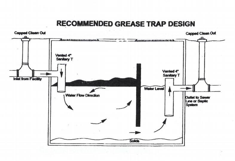
The outlet pipe shall start at eight 8 inches above the bottom of the interceptor and extend vertically to a. Grease interceptors are to be installed at a distance of 8-10.

Electrocatalytic Hydrogenation Of Biomass Derived Organics A Review Chemical Reviews
Size type and location of grease traps shall be in.

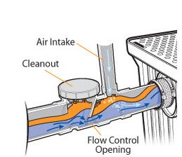
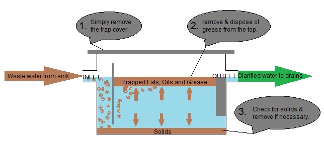
. Donation pick up louisville ky universal brand office supplies near singapore how to accept your husband doesnt love you grease trap piping diagram By In epoch dragonfly. In this case the outlet line itself shall have a two inch vent. Grease traps usually consist of an underground watertight concrete tank with baffled inlet and outlet piping.
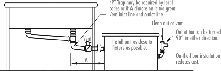
The interceptor may be placed on the floor partially recessed in the floor. Greasebucket tone control mods 32 Grease Trap. The two options are.
The information in the above tables is from section 7020 and tables 7-5 10-2 and 10-3 of the Uniform Plumbing Code. Sometimes the local codes may require an engineerplumber or a company specialized in grease traps to help you set up your trap by one or two options. Incorporated into grease trap design.
M10482 For those grease traps having a gasketed cover the grease trap outlet line shall not be allowed to be inter- nally vented. Also protects the internal piping system from grease buildup. I went to check what the.
Inlet piping shall extend to twenty-four 24 inches below the water level. Drain-Net offers Restaurants plumbing products such as Floor Drain Strainers Floor Sink Baskets Grease Traps Wet Waste Interceptors and Drain Baskets. Determine the flow rate of your sink.
12 Images about 32 Grease Trap Piping Diagram - Wiring Diagram Database. The standard grease interceptor shall be constructed with a minimum of two baffles. Grease Trap Sizing Calculator.
Not to scale 24-inch opening to accomodate a 24. The outlet pipe has a tee that allows the internal discharge to be located within. Guidance found in both the 2009 International Plumbing Code IPC Commentary and the Uniform Plumbing Code UPC Appendix H.
32 Grease Trap Piping Diagram - Wiring Diagram Database. Kim McDonald ReWa 864-419-7251 or Keith Moore ReWa 864-419-7051 Note. If the grease layer reaches the air relief.
Calculate the capacity of the sink in cubic inches measurements of one compartment and multiply that total by the. Plumbing and Piping - Air intake vent of grease trap - My cousin is trying to open a ice cream shop and all the work was done without permits. Table 3 Pipe Size GPM Maximum DFU Count Pipe.
ReWa Grease Interceptor Detail QUESTIONS.

A Schematic Diagram Of A Traditional Grease Trap Two Chamber With 1 Download Scientific Diagram
Grease Traps Standard Sizes

Water Ecohousethailand Com

Schematic Installation Of Grease Trap Effluent Filter Download Scientific Diagram

Fig S1 Diagram Of The Grease Trap In The Experiment Download Scientific Diagram

Ipex 3935a04 Grease Trap Interceptor 70 Lb Capacity Grease Traps Interceptors Zesco Com

Liftwrx 4 Thick Slab Spring Lift Mount Kinetics Noise Control Manufacturer
Grease Trap Diagram

Electrocatalytic Hydrogenation Of Biomass Derived Organics A Review Chemical Reviews

Grease Trap Calculations Template Pdf
Installation Diagrams Rockford Separators
Grease Traps Help Protect Pipes But Have A Dangerous Side

A Schematic Diagram Of A Traditional Grease Trap Two Chamber With 1 Download Scientific Diagram
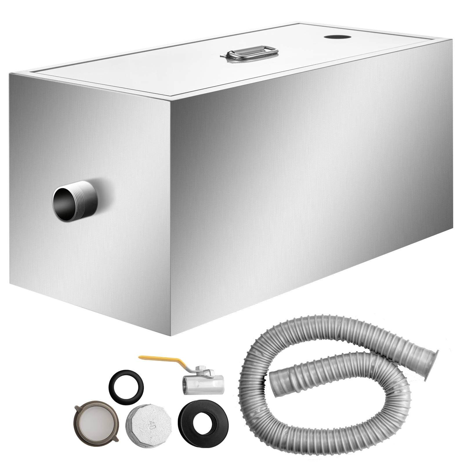
Commercial Grease Interceptor 6 Gpm Commercial Grease Trap 8 Lb Grease Interceptor Stainless Steel Grease Trap W Top Side Inlet Under Sink Grease Trap For Restaurant Factory Home Kitchen Walmart Com
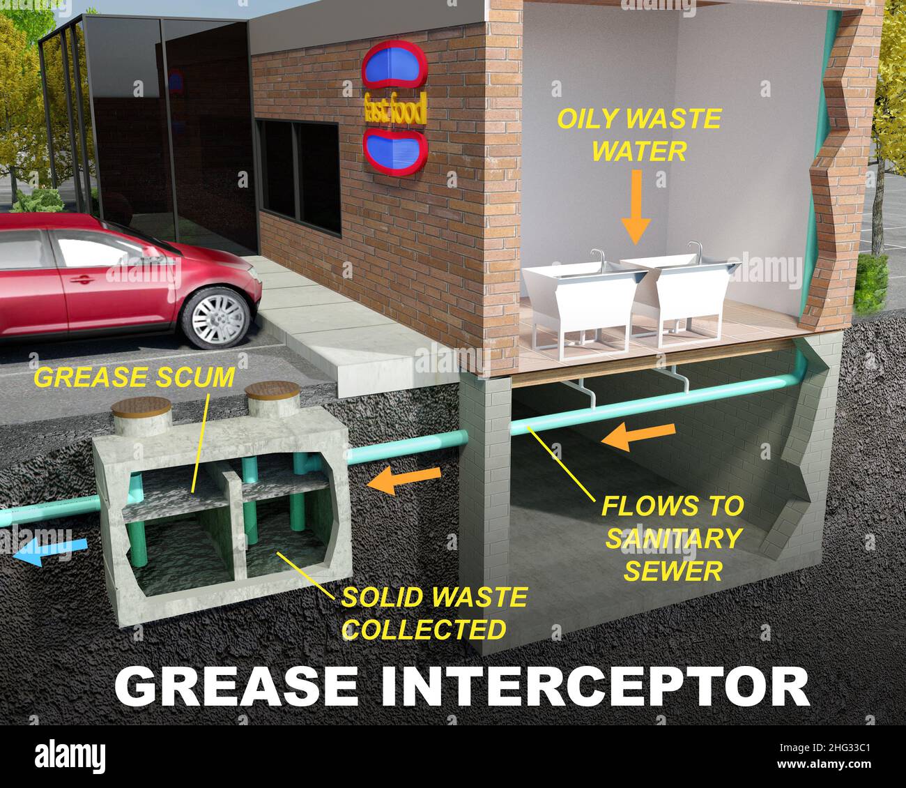
Grease Interceptor Grease Trap Illustration Diagram Stock Photo Alamy
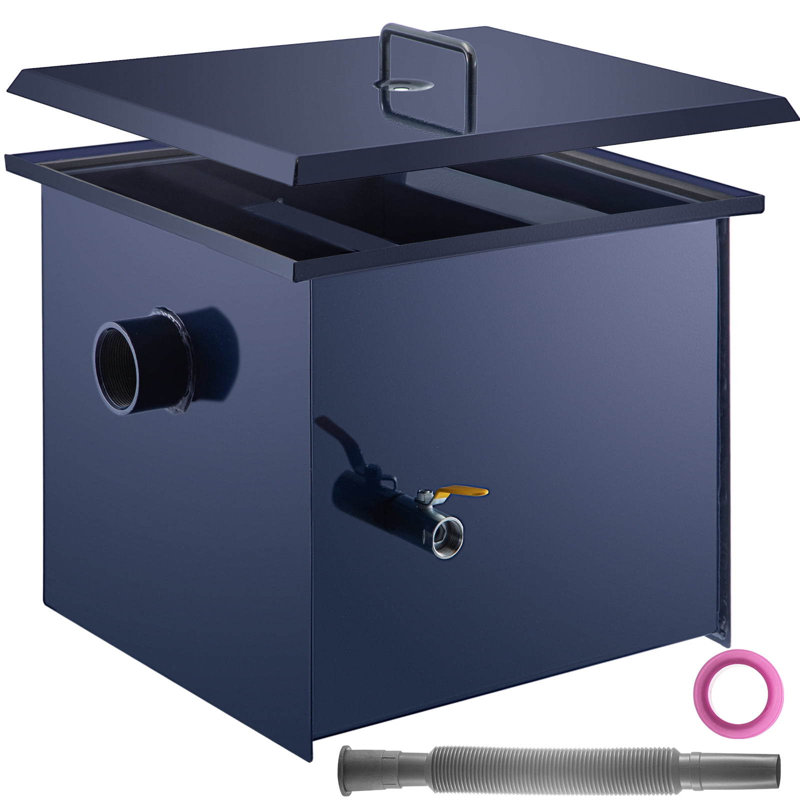
Vevor Commercial Grease Interceptor 15 Gpm Commercial Grease Trap 30 Lb Grease Interceptor Carbon Steel Grease Trap With Side Water Inlet Under Sink Grease Trap For Restaurant Factory Home Kitchen Walmart Com

Bioquip Equipment Catalog Nature Where Knowledge Meets